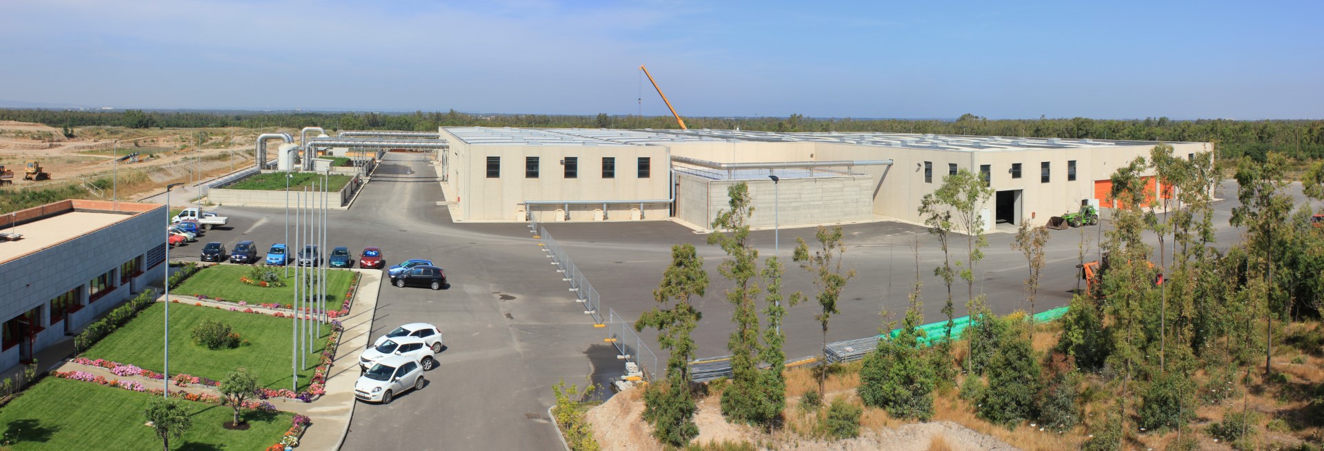
Municipal Solid Waste (MSW) treatment and disposal facility.
-
Active service
Characteristics and operation of the MSW treatment plant
The MSW treatment plant is built in accordance with the highest standards of safety and environmental protection.
The buildings where unloading and treatment operations take place are equipped with dedicated exhaust air “capture and extraction” systems designed to reduce odorous emissions from waste and prevent their dispersion outside the facility.
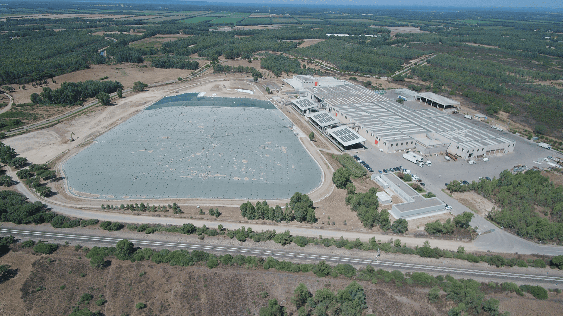
The plant covers an area of approximately 21.5 hectares, of which just under 14 hectares are occupied by industrial buildings, internal and perimeter roadways, the office building, the storage area for mature compost, waste storage areas, yards and green spaces, as well as the service landfill for the final disposal of non-recoverable or non-recyclable processing residues and the related buffer zones designated as green areas.
The facility is composed of the following treatment and disposal sections:
1. A line dedicated to the recovery of organic fractions from separate waste collection (composting plant);
2. A recovery line for dry fractions originating from municipal or private separate collection systems;
3. A separation and treatment line for mixed (unsorted) waste;
4.Service landfill.
The plant sections are briefly described below:
1) Composting plant
This is the line dedicated to the recovery of organic waste (“wet fraction”) collected through separate collection, for the production of high-quality compost suitable for agricultural use as an organic soil improver.
The authorized treatment capacity is 22,700 t/year of waste from separate collection (organic fraction and market waste) and green waste (grass cuttings and pruning residues); however, depending on the needs of the regional catchment area, higher quantities are frequently authorized.
Organic and market waste are unloaded by delivery vehicles in the reception area and then conveyed to the processing line consisting of a bag opener and a mixer. Woody residues are shredded and subsequently fed into the mixer loading line. Within the mixer, the organic fraction and the shredded woody material (the latter supplemented with lignocellulosic material recovered after final screening) are combined according to a predetermined ratio, typically 30%–40% lignocellulosic material and 70%–60% organic waste (by weight) from separate collection.
The mixer is mounted on load cells and is therefore able to accurately measure the preset quantities. Once the target ratios are reached, an electric motor activates the mixing system, made up of rotating screw conveyors, which homogenize the composting material.
Treatment of the organic matter is carried out through a biostabilization process divided into two main stages:
an initial phase of accelerated bio-oxidation in biocells (sealed reinforced concrete boxes where rapid fermentation of the organic material takes place through controlled air supply);
a subsequent refining phase of accelerated biostabilization on aerated platforms, during which the material continues its stabilization process.
Throughout the biostabilization phases, the biomass mixed with the lignocellulosic structuring material is arranged in windrows approximately 3 m high, a height that helps prevent compaction and allows internal air circulation. This approach significantly accelerates the degradation of organic substances by aerobic microorganisms—a process that occurs naturally but over much longer timeframes.
A system of forced aeration from below (and overhead air extraction in the biocells), combined with a sprinkling system for the windrows, maintains optimal process parameters and effectively controls odour emissions. To support stabilization on the aerated platforms, the windrows are periodically turned.
Once accelerated stabilization is completed, and prior to the final maturation phase, the material is refined through screening in order to obtain a product of suitable quality for agricultural use.
The screened material is then stored in windrows within the maturation area and may be released for external use as fertilizer only after a total composting cycle of 90 days and following the acquisition of positive laboratory test results for each production batch, in compliance with Legislative Decree No. 75/2010, which regulates the use of compost as fertilizer.
Exhaust air is conveyed to a dual treatment system consisting of water scrubbers and biofilters.
The following NON-HAZARDOUS municipal, similar (assimilable), and special wastes are accepted for treatment in the composting line:
EWC Code – Description – Authorized Operation
19 05 01 – Uncomposted fraction of municipal and similar wastes – R13 / R3
19 12 07 – Wood other than that referred to in code 19 12 06 – R13 / R3
20 01 08 – Biodegradable kitchen and canteen waste – R13 / R3
20 02 01 – Biodegradable waste – R13 / R3
20 03 02 – Market waste – R13 / R3
Operations are carried out on a single daily shift from Monday to Saturday, generally from 7:00 a.m. to 1:20 p.m.
Key operational data
Average annual quantity of OFMSW and green waste processed over ten years of operation: more than 23,000 tonnes per year
Average production of quality compost: more than 6,000 tonnes per year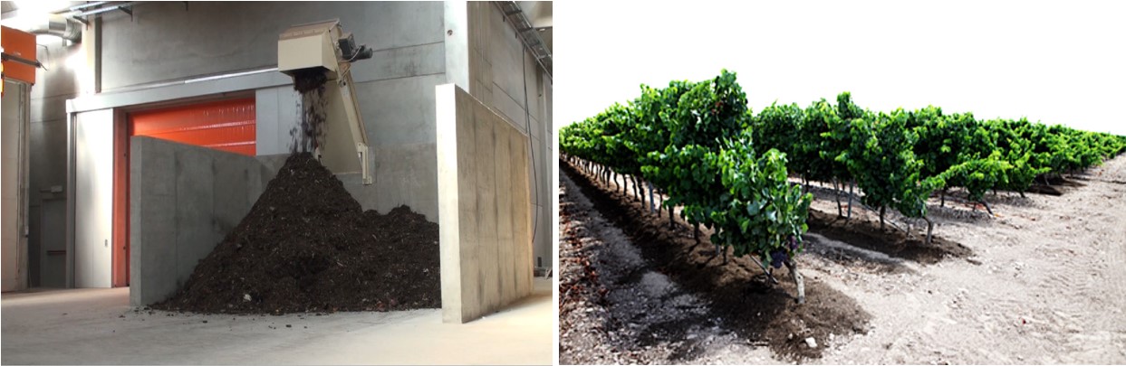
The composting plant holds the CIC Quality Mark, which subjects the entire process to a control program that includes analytical testing of the product to verify compliance with the applicable regulations.
In addition, procedures are in place to ensure full material traceability and trackability (origin of organic feedstocks, identification of production batches, etc.), as well as verification of the quality and purity of the organic waste streams treated by the facility, in accordance with the program of material composition analyses carried out on the organic fraction collected through separate waste collection systems.
Awards and recognitions received
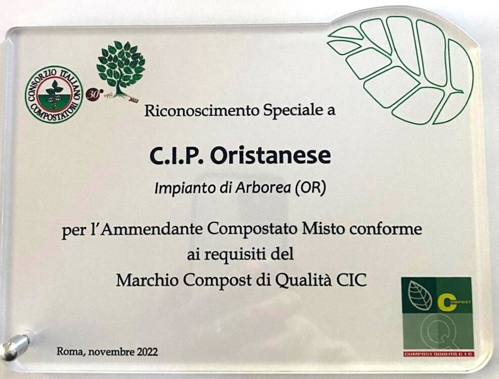
As part of the “Comuni Ricicloni 2018” event organized by Legambiente, held in Rome on 27 June 2018, CIPOR was awarded by the Italian Composting Consortium (C.I.C.) for both the quality of the compost produced and the high standard of organic waste collection in the Province of Oristano.
This recognition was granted because the material purity of the collected organic waste in the area exceeded 98.5%. Furthermore, in 92% of cases, the bags used for the separate collection of the organic fraction were found to be biodegradable and compostable, and therefore suitable for proper use.
2) Recovery plant for mono-material and multi-material separate collections
This line is dedicated to the recovery of dry fractions from municipally operated separate collection systems, aimed at recovering valuable materials such as paper/cardboard, glass, plastics, and metals.
The maximum authorized treatment capacity of this line is 34,500 tonnes per year of municipal, similar (assimilable), and special waste. Its purpose is to carry out advanced sorting of dry fractions collected separately at both municipal and private levels.
The line is capable of treating the following waste streams: single-material and multi-material plastics, paper and cardboard, and single-material glass.
The treatment platform for dry fractions from separate collection is configured as a single processing line that can operate alternatively as:
1. a manual treatment and recovery line for quality control of cellulosic fractions (paper and cardboard);
2. a sorting platform for mixed or single-material waste, mainly consisting of plastic waste from municipal separate collection systems.
SELECTION OF CELLULOSIC FRACTIONS
The manual treatment and recovery of cellulosic fractions have been designed to allow sorting operations to be carried out with maximum simplicity and operational flexibility.
The cellulosic materials to be processed for recovery may be unloaded directly onto the floor adjacent to the feeding pit of the treatment line. Alternatively, when materials are already pre-sorted at the collection stage (e.g. cardboard), they may be unloaded directly onto the press feed conveyor and sent straight to compaction, bypassing the sorting treatment phase.
As no bag-opening operation is required, once the cellulosic fractions are unloaded onto the ground they are fed into the sorting line by a wheeled loader, which supplies the hopper of a mobile conveyor belt that, in turn, feeds the manual inspection line located inside the sorting cabin.
Manual sorting allows the different cellulosic fractions—such as paper, mixed paper, coated paper, Tetra Pak, etc.—and the reject fraction to be separated using either an “active” or “passive” sorting approach, through dedicated manual picking stations.
All selected fractions are conveyed to the underlying storage boxes, from which they are discharged—after opening the purpose-built metal rolling gates—onto the feed conveyor of the baling press.
The baling press then carries out the compaction of the various sorted materials.
SELECTION OF SINGLE-MATERIAL AND MULTI-MATERIAL PLASTIC PACKAGING
The treatment and recovery of mixed or single-material waste streams consisting mainly of plastic waste from municipal separate collection—primarily cans and plastics—have been designed to allow recovery operations to be carried out with maximum simplicity and operational flexibility.
The plastic materials to be processed for recovery are unloaded into a dedicated enclosed area, bounded by reinforced concrete retaining walls, used for storage and quality control. Alternatively, when materials have already undergone preliminary sorting during collection, they may be unloaded directly onto the press feed conveyor and sent straight to the baling press, bypassing the sorting phase.
As bag opening is required, once the plastic fractions are unloaded onto the ground they are fed into the hopper of a rotary bag opener equipped with retractable blades, which discharges the waste onto the feed conveyor of the rotary trommel screen.
Where bag opening is not required, the materials can be sent directly to the sorting line by unloading them into the receiving pit, from which they are conveyed by a dedicated conveyor belt to the mechanical sorting stage.
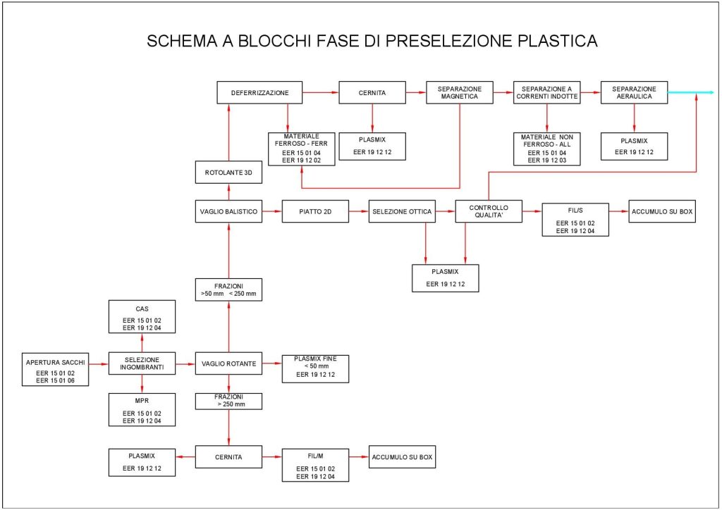
The first mechanical sorting step is carried out by a rotary trommel screen, installed immediately downstream of the bag opener, which allows separation of the FIL/M fraction from the remaining waste.
Downstream of the bag opener, before feeding the rotary trommel screen, two quality-control stations are installed.
The output streams from the rotary screen are as follows:
Oversize (over-screen): plastic film with dimensions greater than 250 mm, recovered as the FIL/M fraction;
Undersize (under-screen): plastic film with dimensions less than 250 mm, used to recover the FIL/S fraction, and the heavy rolling fraction, consisting mainly of bottles and, where joint collection is practiced, also cans (rolling material);
Fine plasmix fraction. < 50 mm.
Each of the above fractions is conveyed by dedicated conveyor belts to different treatment routes, namely:
1. The fraction > The >250 mm fraction is conveyed by conveyor belts into the sorting cabin, where manual sorting of the FIL/M fraction is carried out using a “passive” selection method, and then discharged into a dedicated existing storage box.
2. The fraction < The <50 mm fraction exiting the rotary screen and the ballistic separator is discharged into storage containers for fine plasmix.
3. The fraction < The <250 mm fraction is discharged onto a conveyor belt and conveyed to the ballistic separator, from which three further distinct fractions are obtained.
The first fraction exiting the ballistic separator is sent to an optical sorter for the selection of the FIL/S fraction, which is discharged via conveyor belts into a dedicated storage box. Downstream of the optical sorter, a quality-control station has been предусмотрed to inspect the selected small-size film in order to remove any reject materials or still-recoverable rolling items, which are redirected to further automatic optical sorting.
Before the rolling plastic fraction is conveyed to the automatic optical sorting section, it is subjected to an additional treatment step for the separation of light materials using a dedicated air separation system.
The third fraction consists of fine PLASMIX material.
If required, depending on the type and quality of the incoming material, the mechanized treatment can be omitted by bypassing the ballistic separator via reversal of the reversible feed conveyor belt that supplies the separator.
Manual sorting allows the different plastic fractions and the reject fraction to be separated using either an “active” or “passive” approach, through the use of one double manual sorting station.
Before being sent to the automated sorting line, the residual fraction is in any case subjected to ferrous separation by means of an in-line belt magnetic separator and an additional drum separator installed at the head of the conveyor belt, as well as to the separation of non-ferrous metals (aluminium cans).
All sorted fractions and rejects are conveyed to the underlying storage boxes, from which they are discharged—after opening the purpose-built metal rolling gates—onto the feed conveyor of the baling press.
In order to carry out plastic waste sorting using the optical detectors required by CO.RE.PLA. specifications, a dedicated section has been installed inside Building 2, which is fed directly, via conveyor belts, from the processing line located in Building 1.
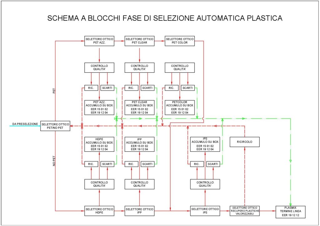
The first optical sorting stage separates PET from non-PET material and is performed by a dedicated sorter with a working width of 2,400 mm. The PET discharged from this unit is conveyed by conveyor belt to a second optical sorter for the selection of light-blue PET (PET “azzurrato”) [positive fraction]. From here, the light-blue PET is transferred via conveyors to the dedicated storage box for PET Azzurrato.
The negative fraction from the light-blue PET sorter is conveyed by conveyors to a further optical sorter for the extraction of clear PET, whose positive fraction is discharged, via an existing conveyor belt, into the storage box dedicated to clear PET (PET CLEAR).
The negative fraction from this sorter is then conveyed to another optical sorter for the extraction of colored PET, whose positive fraction is discharged into the storage box dedicated to colored PET (PET COLOR).
The negative fraction from the PET COLOR sorter is conveyed by conveyor belts to the final optical sorter, which carries out positive selection of bottles and containers for recirculation, while the remaining waste is directed to PLASMIX storage.
The non-PET material coming from the first sorter is conveyed by conveyor belt to the optical sorter that performs the selection of HDPE [positive fraction]. The recovered HDPE is discharged via an existing conveyor into the dedicated storage box for HDPE.
The negative fraction from the HDPE sorter is conveyed to the optical sorter that extracts IPP [positive fraction], which is discharged into the storage box dedicated to IPP by means of a dedicated conveyor belt.
The negative fraction from the IPP sorter is conveyed by conveyor belt to the existing optical sorter for the extraction of IPS. The positive fraction from this sorter is discharged into the storage box dedicated to IPS.
The negative fraction, via two new conveyor belts, is subsequently conveyed to an additional optical sorter that recovers material not captured by the preceding optical sorters and sends it to the recirculation line for reprocessing. The negative fraction from this last sorter is finally discharged as reject into the storage box dedicated to PLASMIX.
A dedicated recirculation line has been designed for the reprocessing of materials intercepted at the various quality-control stations. This line allows recovery of material that has not been captured by the optical sorters and feeds it back to the head of the optical sorting line.
The purpose of the recirculation system is to increase the overall recovery rate of recyclable plastic materials.
A protected control cabin has been provided for operators responsible for monitoring the output streams from the optical sorters. The cabin is constructed with a steel frame structure, insulated “sandwich” panel cladding, and sliding windows.
Below is the block diagram of the line’s operation:
The platform has been designed to qualify as an Advanced Sorting Center (CSS), meaning a facility capable of performing polymer- and color-based sorting of plastic packaging waste collected through separate collection systems. At the end of the process, the following material streams are obtained:
• Clear PET containers (SELE-CTL/M)
• Light-blue PET containers (SELE-CTA/M)
• Colored PET containers (SELE-CTC/M)
• PE containers (SELE-CTE/M)
• Crates (CAS)
• Mixed polypropylene packaging (SELE IPP/C)
• Polystyrene packaging (SELE IPS/C)
• Packaging film (SELE-FIL/M)
• Rigid polyolefin packaging (SELE-MPR/C)
• Flexible plastic packaging (SELE-FIL/S)
• Plasmix
• Plasmix fine
Downstream of the various sorting stages, the baling press compacts the different sorted material streams.
Waste that is not processed through the sorting line (such as wood, glass, agricultural films, and metals), for which only preliminary cleaning and/or volume reduction through baling (in the case of agricultural films) is required, will be stored in piles or in roll-off containers within the designated areas specified in the authorization.
The following NON-HAZARDOUS municipal, similar (assimilable), and special wastes are admitted for treatment at the recovery platform:
| EWC Code | Description |
| 02 01 04 | Plastic waste (excluding packaging). |
| 15 01 01 | Paper and cardboard packaging. |
| 15 01 02 | Plastic packaging. |
| 15 01 03 | Wooden packaging. |
| 15 01 04 | Metal packaging. |
| 15 01 05 | Composite packaging. |
| 15 01 06 | Mixed-material packaging. |
| 15 01 07 | Glass packaging. |
| 19 12 04 | Plastics and rubber. |
| 20 01 01 | Paper and cardboard. |
| 20 01 02 | Glass |
| 20 01 38 | Wood other than that mentioned in item 20 01 37 |
| 20 01 39 | Plastic |
| 20 01 40 | Metal |
Work activities are carried out in two shifts from Monday to Friday, normally from 6:00 a.m. to 1:30 p.m. and from 1:30 p.m. to 9:00 p.m.
3) Dry and residual waste sorting and treatment facility:
It is a line for the separation and treatment of residual waste after separate collection (dry mixed waste and/or non-separated waste). The material exiting the treatment line consists of two streams: oversize and undersize fractions. The authorized treatment capacity is 30,000 t/year, including waste that is not treated prior to being sent for disposal, such as street-sweeping waste, screening residues, and waste from grit removal.
From the shredder, via conveyor belts, the shredded waste—after ferrous metal removal—is sent to the disc screen, which generates two material streams:
Undersize: a fraction obtained from screening the shredded dry mixed waste to intercept the putrescible organic component. This waste is disposed of in landfill only after stabilization, either loose or compacted into bales.
As the quantities of undersize material to be stabilized are modest, due to the high level of separate collection achieved in the Province of Oristano, it is sufficient to use only the FOS stabilization slab for the treatment of this stream.
The undersize material is deposited, using a wheel loader, on the biostabilization slab dedicated to FOS located in the “biostabilization building.” Once the prescribed respirometric index value has been reached over the required period, the stabilized material—after baling—is loaded onto a plant vehicle and sent to the service landfill with EWC code 19 12 12.
The following waste types are accepted on the residual dry waste line:
| EWC Code | Description |
| 20 03 01 | Mixed municipal waste (unsorted urban waste) |
| 20 03 03 | Street cleaning residues |
| 20 03 07 | Rifiuti ingombranti |
| 19 08 01 | Screening residues |
| 19 08 02 | Grit removal waste |
Work activities are carried out in a single shift from Monday to Saturday, normally from 7:00 a.m. to 1:20 p.m.
The three processing lines are completely separate and are located inside a series of industrial buildings. The buildings cover a total enclosed surface area of approximately 18,000 m², with a maximum height of 9.00 m, and are arranged within a fenced site that includes: access and perimeter roadways, the office building, yards, shelters for the temporary storage of mature compost and waste, biofilters, parking areas, auxiliary facilities, and landscaped green areas.
4) Service landfill
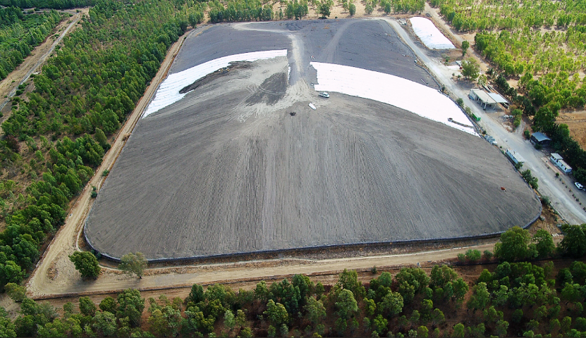
The facility is completed by a storage area for the stockpiling of treatment residues that cannot be recovered or recycled and which, if necessary, have undergone a prior stabilization process aimed at limiting the formation of biogas and leachate. The storage area, known as the service landfill, has a total authorized capacity of approximately 300,000 cubic meters.
The service landfill is divided into three modules, and its construction was carried out in accordance with the provisions of Legislative Decree No. 36 of 13 January 2003. In particular, a bottom and sidewall waterproofing system was installed, consisting of a 100 cm thick clay layer with a permeability coefficient of K = 10⁻⁹ m/s and a 2.5 mm thick HDPE geomembrane. Above this, a 60 cm thick drainage layer was installed, within which a network of micro-perforated pipes collects any leachate, whose presence mainly results from infiltration due to meteorological precipitation.
The leachate is conveyed to a set of watertight tanks located within an above-ground containment basin with a spill-prevention function, and is subsequently loaded onto a tanker truck and sent to a suitable external treatment facility.
In compliance with Legislative Decree No. 36/2003, the installation of a biogas extraction system is also предусмотрed, consisting of collection wells that will be progressively connected to a suction station and a combustion flare.
For the purpose of monitoring the long-term integrity of the HDPE (high-density polyethylene) impermeable membrane, a permanent geoelectric monitoring system was prescribed during the Environmental Impact Assessment (EIA) and Integrated Environmental Authorization (IEA/AIA) procedures and has been installed accordingly.
By comparing the signals received from the various electrodes on a computer terminal, it is possible to locate any leaks in the HDPE liner with an accuracy inversely proportional to the spacing of the grid on which the electrodes were installed.
In order to preserve the integrity of the HDPE geomembrane, a protective system consisting of polyethylene geocells filled with soil was installed along the embankments.
The operating procedures vary depending on whether the deposited waste consists of baled dry fraction or other permitted waste types.
In the case of baled dry fraction (whether derived from the mechanical treatment of dry waste or from the volume reduction of bulky waste subjected to mechanical treatment), unloading is carried out by individually handling the bales using a dedicated forklift or other suitable equipment and placing them in an orderly manner in the unloading area, at an appropriate distance from the side embankments.
The bales will be covered daily with synthetic fabric and/or with a layer of soil in order to prevent the generation of dust or nuisance emissions.
In the presence of strong winds, landfill disposal operations are suspended and the waste is temporarily stored in the storage areas inside the buildings.
The stacking of bales is carried out so as to achieve maximum stability of the pile, in particular by arranging them in a staggered pattern so that each bale rests on the two halves of the underlying bales, thus obtaining a stacking front inclination of approximately 45°. Stacking is limited to a maximum of four bales, reaching an overall height of about 3 m with respect to adjacent areas.
To prevent self-combustion phenomena, the uncovered active working face is kept to the minimum extent strictly necessary.
In the portions of the landfill where disposal operations have been completed, the surface is covered with a layer of soil, finely leveled and modeled with appropriate slopes, then protected with an impermeable HDPE liner in order to prevent: during the summer period, cracking of the cover material with consequent fugitive biogas emissions; and during the winter period, infiltration of rainwater into the waste mass.
Upon completion of the landfill capacity and after the settlement phase, the construction of the final capping cover is planned, followed by planting with native herbaceous and shrub species to restore the site within the local environmental context.
Informazioni ambientali
Integrated Environmental Authorization (IEA)
2025 Tariffs
Further information
Hours: Work is carried out in a double shift from Monday to Friday, generally from 6:00 a.m. to 1:30 p.m. and from 1:30 p.m. to 9:00 p.m.
Directions